The control system is one of the main elements of the rectifier unit. Incorrect operation of the control system often leads to operation failures and even serious accidents, even when the power part itself is functioning properly. 25 years of experience in this field has allowed us to create one of the world’s best control systems for rectifier units. In General, control system has three levels: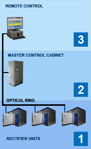
- Single rectifier unit control. Local control cabinet.
- DC substation control. Control of a group of rectifier units, operating one or different loads. Master control cabinet.
- Remote control. It can be either a simple cabinet with a current indicator, control keys and indicator lights, or a complex remote control with SCADA system, hardware and software redundancy, backup manual control panels, technological automation and bridge to ERP systems.
Our control system is highly reliable due to the fact that each “lower” level can function when the “upper” levels or communication channels with them completely fail.
All elements are located in cabinets with IP54 protection, which are equipped with industrial air conditioners if necessary.
Main parts of local control cabinet
Power input and distribution board. It is used for power supply of all internal loads of the rectifier unit: control system, cooling system pumps and fans, transformer control system, current meters, etc. Contains two 0.4 kV independent inputs (one main and one standby) with automatic standby activation.
Programmable logic controller PLC. Performs the main control and protection algorithms, except high-speed current protection. The basic family is the SIEMENS SIMATIC S7-1200/1500. These controllers have developed communication capabilities using most modern data exchange protocols, which makes it easy to integrate them into the company’s automated control systems. Upon customer’s request controllers of other manufacturers could be installed.
High-speed current protection unit. It is based on current relays or relay protection terminals.
Human-machine interface HMI. Its main element is a color graphic panel. For the convenience of operational personnel, the main commands (switching on/off of the main HV circuit breaker, emergency shutdown) and main signals (position of the of the main HV circuit breaker, warnings and trips presence) are duplicated by keys and warning lights on the cabinet door.
The operator’s e interface is organized as a window menu. All the necessary operational and diagnostic information about the operation of the unit is displayed in separate windows. Windows contain animated mnemonic diagrams and fields for displaying of measured values, graphs, visual alarms, and text messages. Special elements allow to perform operational control of the rectifier unit in local control mode and configure the parameters of the control system. If necessary, specific customer-oriented windows could be added. Below is a brief description of the main Windows:
- In the main window, the diagram of the rectifier unit is displayed, indicating the current position of the switching devices, the state of the transformer and cooling system, indicating the measured value of the network winding current, the DC and voltage of the unit, and indicating the operation of warning and emergency alarms.
- The cooling system monitoring window displays a detailed diagram of the cooling system, indicating the equipment in operation and all the monitored parameters, including the measured values of the coolant temperature at the control points, the electrical conductivity of the coolant, the air temperature, etc.
- The event and alarm log window displays an array of messages about changes in the state of the unit’s equipment (such as: switching on/off the HV CB, switching on/off the cooling system pumps, switching the control mode, etc.), an array of warning and trip messages in chronological order. You can view messages separately (for example, only trip and/or warning messages), as well as display only active warning and / or trips.
- In the settings window, you can control and change parameters such as: unit protection settings, automatic control settings, control system coefficients, scaling and simulation of all digital and analog inputs/outputs, etc. For convenience, the parameters are grouped according functional characteristics and equipment. Settings have multi-level access with password protection.
Thyristor firing control system
Nowadays, the thyristor firing control system can only be digital. Any analog system requires periodic adjustment – over time, the parameters of the elements “float away”, which leads to an asymmetry of the control pulses, which, in turn, dramatically increases the content of harmonics. Control accuracy of more than 1% on analog elements is unattainable, in a digital system, phasing of the control system with a power voltage is performed by simply setting a parameter in the settings window, the regulator coefficients change in the same settings window without reducing the load, the current value of the control angle is available in digital form.
The original digital system of our own development has accumulated many years of experience in creating of such systems and has shown high quality of control and reliability. Today it is installed and successfully operates in several dozens of rectifier units.
The thyristor firing control system from “ETS Engineering” has the following distinctive features:
- fully digital system;
- no asymmetry of control pulses;
- digital adaptive regulator with the ability to dynamically change coefficients;
- high quality regulation (up to 0.5%);
- the presence of two synchronization inputs, which eliminates current surges in case of standby operation;
- software correction for synchronization inputs, which allows to configure synchronization when a transformer connection group is changed only by correcting a single software coefficient;
- transmission of control pulses to thyristors via optical channels;
- the high-power output signal of the thyristor control modules guarantees reliable switch-on of the thyristor in all conditions.
Master control cabinet
Usually it is installed if there are several units operating in parallel. It performs the regulating of the total DC current, measures the total current and voltage, and serves for communication with technological automation and telemechanic systems. On the basis of the central control cabinet, especially if it is installed near or on the control panel, the remote control of the units is performed.
Remote control
It is used for remote control of the unit and monitoring of its operating modes. Depending on specific requirements, it can be either a simple setpoint / current indicator with a number of control lamps and switches, or a branched remote control with workstations based on industrial computers with hardware and software redundancy, a SCADA system, data transmission to the ERP system, SMS, remote monitoring, etc.